
Meyer Sound LINA
Amazing audio from a very compact system.

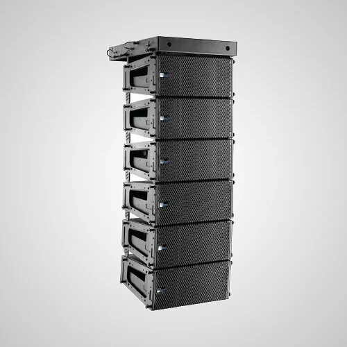
Experience LINA: Ultra-Compact Line Array Loudspeaker
Completing the family and easily the smallest and lightest in the series, LINA and its companion control element 750-LFC bring the inherent linearity, low distortion, and exceptional power-to-size ratio of LEO Family technology to a wider range of applications and venues.
Taking advantage of the existing MINA footprint, LINA boasts new drivers and an updated amplifier and signal processing package that, along with an improved power supply, enables higher peak output.
Brand: Meyer Sound
Product Description: LINA
Category: Line Array Loudspeaker
Available Stock: 10 Units
Price: Attractive daily hire rates or long-term rental options
LINA Product Info & Key Features
Small footprint and narrow width are ideal for small venues and fill applications
Amazing power-to-size ratio
Exceptional linearity and transient reproduction at any level, high peak power output, and extremely low distortion
Self-powered to simplify setup and increase reliability
Flexible rigging for flown and ground-stacked arrays
Easy integration with Meyer Sound’s LEOPARD line array loudspeaker, and the 750-LFC and 900-LFC low frequency control elements
Call 1300 814 568 or email events@cmgav.com.au
Meyer Sound LINA Specifications
ACOUSTICAL
Operating Frequency Range: 65 Hz – 18 kHz
Phase Response: 100 Hz – 18 kHz ±45°
Linear Peak SPL: 132 dB with 19 dB crest factor (M-noise), 128 dB (Pink noise), 130 dB (B-noise)
COVERAGE
Horizontal Coverage: 100°
Vertical Coverage: Varies, depending on the array length and configuration
TRANSDUCERS
Low Frequency: Two 6.5-inch long-excursion cone drivers; 4 Ω nominal impedance
High Frequency: One 3-inch diaphragm compression driver coupled to a constant-directivity horn through a patented REM® manifold; 8 Ω nominal impedance
AUDIO INPUT
Type: Differential, electronically balanced
Maximum Common Mode Range: ±15 V DC, clamped to earth for voltage transient protection
Connectors: XLR 3-pin female input with male loop output. Optional XLR 5-pin connector to accommodate both balanced audio and RMS signals.
Input Impedance: 10 kΩ differential between pins 2 and 3
Wiring:
Pin 1: Chassis/earth through 1 kΩ, 1000 pF, 15 V clamp network to provide virtual ground lift at audio frequencies
Pin 2: Signal +
Pin 3: Signal ‐
Pin 4: RMS
Pin 5: RMS
Case: Earth ground and chassis
Nominal Input Sensitivity: 0 dBV (1.0 V rms) continuous is typically the onset of limiting for noise and music
Input Level: Audio source must be capable of producing of +20 dBV (10 V rms) into 600 Ω to produce the maximum peak SPL over the operating bandwidth of the loudspeaker.
AMPLIFIERS
Type: 3-channel, Class-D
Total Output Power: 1950 W peak
THD, IM, TIM: < 0.02%
Cooling: Convection
AC POWER
Connector: powerCON 20 input with loop output
Automatic Voltage Selection: 90–265 V AC, 50–60 Hz
Safety Rated Volted Range: 100–240 V AC, 50–60 Hz
Turn-on and Turn-off Points: Turn‐on: 90 V AC turn-on, no turn-off; internal fuse-protection above 265 V AC
CURRENT DRAW:
Idle Current: 0.25 A rms (115 V AC); 0.25 A rms (230 V AC); 0.29 A rms (100 V AC)
Max Long‐Term Continuous Current (>10 sec): 2.3 A rms (115 V AC); 1.16 A rms (230 V AC); 2.8 A rms (100 V AC)
Burst Current (<1 sec): 3.9 A rms (115 V AC), 1.7 A rms (230 V AC), 4.5 A rms (100 V AC)
Maximum Instantaneous Peak Current: 8.8 A peak (115 V AC), 4.0 A peak (230 V AC), 9.2 A peak (100 V AC)
Inrush Current: < 20.0 A peak
RMS NETWORK
Equipped with two-conductor twisted-pair network, reporting all operating parameters of amplifiers to system operator’s host computer.
PHYSICAL
Dimensions: W: 20.27 in (515 mm) x H: 8.38 in (213 mm) x D: 15.32 in (389 mm)
Weight: 43 lb (19.5 kg)
Enclosure: Premium multi-ply birch, slightly textured black finish
Protective Grille: Powder-coated, hex-stamped steel with acoustical black mesh
Rigging: End frames with captive GuideALinks secured with 0.25 in x 0.53 in quick release pins that allow 0° to 11° splay angles. M6 attachment points for optional MYA-MINA/LINA mounting yoke and MUB- MINA/LINA U-bracket
MANUFACTURER NOTES
Loudspeaker system predictions for coverage and SPL are available in Meyer Sound’s MAPP System Design Tool.
Recommended maximum operating frequency range. Response depends on loading conditions and room acoustics.
Linear Peak SPL is measured in free-field at 4 m referred to 1 m. Loudspeaker SPL compression measured with M-noise at the onset of limiting, 2-hour duration, and 50°C ambient temperature is <2 dB. M-noise is a full bandwidth, (10Hz–22.5kHz) test signal developed by Meyer Sound to better measure the loudspeaker’s music performance. It has a constant instantaneous peak level in octave bands, a crest factor that increases with frequency, and a full bandwidth Peak to RMS ratio of 18 dB. Pink noise is a full bandwidth test signal with Peak to RMS ratio of 12.5 dB. B-noise is a Meyer Sound test signal used to ensure measurements reflect system behavior when reproducing the most common input spectrum, and to verify there is still headroom over pink noise.
Pins 4 and 5 (RMS) only included with XLR 5-pin connector that accommodates both balanced audio and RMS signals.
Peak power based on the maximum unclipped peak voltage the amplifier will produce into the nominal load impedance.
AC power cabling must be of sufficient gauge so that under burst current rms conditions, cable transmission losses do not cause the loudspeaker’s voltage to drop below the specified operating range.
IMPORTANT: CMG strive to provide the most accurate and complete equipment description and item specifications, including weight, rigging, power requirements and recommended use. All product information has been sourced from the original equipment manufacturer (or Australian distributor) and is based on the manufacturers standard specifications. Actual specifications for this equipment may differ. It is highly recommended that all equipment details are confirmed with our team PRIOR TO USE as the supplier, as the latter (CMG Audio Visual Pty Ltd) cannot be held accountable for any inaccuracies.