
Meyer Sound 900-LFC
Supercharge your bass line and feel every beat.

Experience 900-LFC: Compact Low-Frequency Control Element
Take advantage of the linearity and fidelity of the flagship 1100-LFC, in a smaller, lighter package that’s ideal for scalable systems. Whether you’re in a club, theatre, theme park, or on tour, the 900-LFC delivers breathtaking bass, from the front row to the back of the house.
The 900-LFC Low-Frequency Control Element extends the response of mid-sized P.A. systems to 35 Hz, revealing the nuances of your mix, down to the deepest bass with total accuracy.
Brand: Meyer Sound
Product Description: 900-LFC
Category: Low-Frequency Control Element, Subwoofer
Available Stock: 36 Units
Price: Attractive daily hire rates or long-term rental options
900-LFC Product Info & Key Features
Compact cabinet with small footprint and extraordinary power-to-size ratio;
High peak power output with extremely low distortion;
Exceptional linearity, transient reproduction, and low-frequency clarity;
Self-powered for simplified setup and increased reliability;
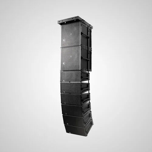
Stackable and flyable in regular and cardioid arrays, with tilt and splay options;
Integral pole-mount receptacle easily pairs the subwoofer with ULTRA Series loudspeakers.
Call 1300 814 568 or email events@cmgav.com.au
Meyer Sound 900-LFC Specifications
ACOUSTICAL
Operating Frequency Range: 30 Hz – 125 Hz
Frequency Response: 32 Hz – 115 Hz ±4 dB
Phase Response: 40 Hz – 110 Hz ±30°
Linear Peak SPL: 133 dB with crest factor >10 dB (M-noise), 133 dB (Pink noise), 134.5 dB (B-noise)
COVERAGE
Coverage: 360° (single unit); varies with number of units and configurations
TRANSDUCERS
Low Frequency: One 18-inch, dual-coil, long-excursion cone driver; 2Ω nominal impedance
AUDIO INPUT
Type: Differential, electronically balanced
Maximum Common Mode Range: ±15 V DC, clamped to earth for voltage transient protection
Connectors: XLR 5-pin female input with male loop output; XLR 3-pin female connectors available to accommodate only balanced audio (no RMS signals)
Input Impedance: 10 kΩ differential between pins 2 and 3
Wiring:
Pin 1: Chassis/earth through 1 kΩ, 1000 pF, 15 V clamped network to provide virtual ground lift at audio frequencies
Pin 2: Signal +
Pin 3: Signal ‐
Pin 4: RMS
Pin 5: RMS
Case: Earth ground and chassis
Nominal Input Sensitivity: 6.0 dBV (2.0 V rms) continuous is typically the onset of limiting for noise and music
Input Level: Audio source must be capable of producing +20 dBV (10 V rms) into 600 Ω to produce the maximum peak SPL over the operating bandwidth of the loudspeaker
AMPLIFIERS
Type: Two-channel, open-loop, class D
Total Output Power: 3100 W peak
THD, IM, TIM: < 0.02%
Cooling: Convection
AC POWER
Connector: powerCON 20 input with loop output
Automatic Voltage Selection: 90–265 V AC, 50–60 Hz
Safety Rated Volted Range: 100–240 V AC, 50–60 Hz
Turn-on and Turn-off Points: 90 V AC turn-on, no turn-off; internal fuse-protection above 265 V AC
CURRENT DRAW:
Idle Current: 0.60 A rms (115 V AC), 0.49 A rms (230 V AC), 0.63 A rms (100 V AC)
Max Long‐Term Continuous Current (>10 sec): 4.9 A rms (115 V AC); 2.5 A rms (230 V AC); 5.2 A rms (100 V AC)
Burst Current (<1 sec): 8.8 A rms (115 V AC), 4.7 A rms (230 V AC), 11.0 A rms (100 V AC)
Maximum Instantaneous Peak Current: 18.2 A peak (115 V AC), 9.2 A peak (230 V AC), 20.6 A peak (100 V AC)
Inrush Current: < 20 A peak
RMS NETWORK
Equipped with two-conductor twisted-pair network, reporting all operating parameters of amplifiers to system operator’s host computer.
PHYSICAL
Dimensions (without Rigging): W: 27.43 in (697 mm) x H: 24.43 in (621 mm) x D: 24.89 in (632 mm)
Dimensions (with Rigging): W: 27.47 in (698 mm) x H: 24.43 in (621 mm) x D: 24.89 in (632 mm)
Weight (without Rigging): 136 lb (61.7 kg)
Weight (with Rigging): 159 lb (72.1 kg)
Enclosure: Premium multi-ply birch with slightly textured black finish
Protective Grille: Powder-coated, hex-stamped steel with acoustical black mesh
Rigging: Optional end frames with captive GuideALinks secured with 0.3125 in x 0.63 in quick release pins that allow 0°, 1.25°, 2.5°, 3.75°, or 5° splay angles; detachable side handles. Rigging supports ground-stacked, flown, and cardioid configurations.
Pole Mount: U.S. version: 1.5 in (38 mm) / E.U. version: 1.375 in (35 mm and M20 thread at the bottom)
MANUFACTURER NOTES
Loudspeaker system predictions for coverage and SPL are available in Meyer Sound's MAPP System Design Tool.
Recommended maximum operating frequency range. Response depends on loading conditions and room acoustics.
Measured in half-space with pink noise at 4 m, 1/3-octave frequency resolution.
Linear Peak SPL is measured in half-space at 4 m referred to 1 m. Loudspeaker SPL compression measured with M-noise at the onset of limiting, 2-hour duration, and 50-degree C ambient temperature is <2 dB. M-noise is a full bandwidth, (10 Hz–22.5 kHz) test signal developed by Meyer Sound to better measure the loudspeaker’s music performance. It has a constant instantaneous peak level in octave bands, a crest factor that increases with frequency, and a full bandwidth Peak to RMS ratio of 18 dB. The presence of a greater-than (>) symbol with regard to crest factor indicates it may be higher depending on EQ and boundary loading. Pink noise is a full bandwidth test signal with Peak to RMS ratio of 12.5 dB.B-noise is a Meyer Sound test signal used to ensure measurements reflect system behavior when reproducing the most common input spectrum, and to verify there is still headroom over pink noise.
Pins 4 and 5 (RMS) only included with XLR 5-pin connector that accommodates both balanced audio and RMS signals.
Peak power based on the maximum unclipped voltage the amplifier will produce into the nominal load impedance.
AC power cabling must be of sufficient gauge so that under burst current rms conditions, cable transmission losses do not cause the loudspeaker’s voltage to drop below the specified operating range.
IMPORTANT: CMG strive to provide the most accurate and complete equipment description and item specifications, including weight, rigging, power requirements and recommended use. All product information has been sourced from the original equipment manufacturer (or Australian distributor) and is based on the manufacturers standard specifications. Actual specifications for this equipment may differ. It is highly recommended that all equipment details are confirmed with our team PRIOR TO USE as the supplier, as the latter (CMG Audio Visual Pty Ltd) cannot be held accountable for any inaccuracies.